
Variable frequency drive is a technique used to control the speed and frequency of AC induction motors thus it is also known as adjustable speed drive or variable speed drive. As 25% of the world’s electricity is consumed by AC motor and the problem with these motors is large starting inrush current. When the motor starts a large current is drawn by the motor, it continues until the motor reaches the synchronous speed. This high current not only produces heat but also reduces the life of electrical equipment and power consumption increases. Thus, there is a need to reduce this current.
How to test VFD with a multimeter?
Working of Variable Frequency Drive
In a VFD, the voltage and frequency of the motor are controlled using a technique named PWM (Pulse Width Modulation). There are so many other techniques used to reduce the current of the motor like soft starters. But the benefits of variable frequency drive are more than soft starters. Like it provides energy to electrical appliances according to demand. It enhances the life of the equipment and saves energy.
components used
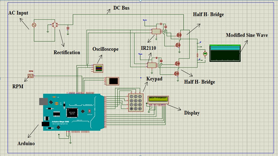
- Arduino
- Rectifier
- Inverter circuit
- DC Bus
- LCD
- Keypad
- Half H-Bridge
- IR2110
- Connecting wires
When a fixed AC voltage is fed into AC to DC rectifier the AC voltages are converted into DC voltages. Which are further directed towards the DC bus which comprises capacitors and is used to store voltages and remove ripples in the DC voltage thus smoothing out the waveform. Invertor is the last section which is the most important one because it performs the DC to AC conversion by approximating the square waveform with that of sine waveform whose pulse is adjusted to control the voltages and frequency of motors. A very important tool of variable frequency drive is PWM which is the key technique for controlling motor speed.
you may like to read” How to get back Virtual Terminal in Proteus? “
Diagrams
The image below is the working principle of VFD

The figure below is Proteus simulation of Speed control of induction motor by V/f method experiment

Results (Variable Frequency Drive)
The images below are showing the speed at different frequencies


As you can see from the results that frequency and speed are directly proportional to each other. Decreasing the frequency speed of the motor will decrease and increasing the frequency results in increasing the speed of the motor.
you man like to read ” Throttle Based Electric Bicycle Controller Design“
Coding(VFD control of induction motor MATLAB code)
#include <TimerOne.h>

#include <LiquidCrystal.h>	//we included library for lcd

LiquidCrystallcd(40, 42,44, 46, 48, 50);	//this is for LCD pin attachments with Arduino
 this way we tell our Arduino software that LCD pins are these pins on Arduino

byte narray[20];	//Array for 20 words intnarray_c=0;
intu_u=0;

//////////

#include <Keypad.h>
long intdt=0;
long intlt=0; l
ong intnt=0;
const byte ROWS = 4;	//four rows

const byte COLS = 3;	//three columns char keys[ROWS][COLS] = {
{'1','2','3'},

{'4','5','6'},

{'7','8','9'},

{'*','0','#'}

};

byte rowPins[ROWS] = {22, 24, 26, 28};	//connect to the row pinouts of the keypad
 byte colPins[COLS] = {30, 32, 34};     //connect to the column pinouts of the keypad


Keypad keypad = Keypad( makeKeymap(keys), rowPins, colPins, ROWS, COLS );

/////////////////


boolean ok=0;

void setup() {

pinMode(5,OUTPUT);	// output on pin5

pinMode(6,OUTPUT);	// output on pin6

pinMode(7,OUTPUT);	// output on pin7

pinMode(8,OUTPUT);// output on pin8
pinMode(13,OUTPUT);// output on pin13
pinMode(11,OUTPUT);	// output on pin11
pinMode(12,OUTPUT);		// output on pin12
pinMode(2,INPUT_PULLUP);
Serial.begin(9600);// Initialize serial communications with the PC
while (!Serial);	// while loop
// Do nothing if no serial port is opened (added for Arduinos based on
ATMEGA32U4)

pinMode(10,OUTPUT);	// output on pin10 lcd.begin(16, 2);
lcd.print("  Single Phase ");	//output on LED lcd.setCursor(0,1);
lcd.print("   VFD System  ");	//output on LED delay(3000);		//delay
lcd.clear();	// clear the lcd

lcd.print("Enter Frequency!");	//output on LED lcd.setCursor(0,1);
ok=0;

String datav=""; do
{

char key = keypad.getKey();

if (key){	//If Loop

if(key=='#')

{

datav="";

lcd.clear();

lcd.print("Enter Frequency!");	//Entering Frequency lcd.setCursor(0,1);
}else if(key=='*')	//Else if

{

ok=1; Serial.println(datav);
}else

{

datav+=key;	// Entering data

}

Serial.println(key);

lcd.print(key);	//Print or show the enter data

}

}while(ok==0); lcd.clear();
lcd.print("Frequency:");
intuu=datav.toInt();
if(uu<10){uu=10;} if(uu>100){uu=100;}
lcd.print(uu);lcd.print("Hz");

long time_period=(float)(1000000/uu);

Serial.print("Time Period in Microcesonds : ");
Serial.println(time_period);
long half_time_period=time_period/2;

Serial.print("Half Time Period in Microcesonds : ");
Serial.println(half_time_period);

Timer1.initialize(half_time_period);

Timer1.attachInterrupt( timerIsr );	// attach the service routine here DDRH=0xff;
attachInterrupt(0,my_interrupt,FALLING);	//interrupt enabling

}

void my_interrupt()

{

nt=micros();
dt=nt-lt; lt=nt;
}

bool tog=0;
void timerIsr()
{

PORTH=0b00000000;

delayMicroseconds(500);
tog=tog^1;
if(tog)//h3 6 h4 7 h5 8

{

PORTH=0b00001000;

}else

{

PORTH=0b00010000;

}

// Toggle LED

// digitalWrite( 13, digitalRead( 13 ) ^ 1 );


}

void loop() { //loop lcd.clear();
lcd.print("RPM: ");
float rpm=(float)dt/1000000;	//Divide the time on 1000000 samples rpm=(float)1/rpm;
rpm=rpm*60;
lcd.print(rpm,1);
lcd.print("R/m");
Serial.print("RPM Measured : ");
Serial.print(rpm,1);
Serial.println("Rev/M");
delay(100);
}

After reading "Speed Control of Induction motor using VFD" you will be able to make your own
Variable Frequency drive either for motor or your project. We have tried to cover everything
still if you have any suggestions or questions, Let us know in the comment section below.
Can you upload the simulation video of this project on your youtube channel?
ok
Hello, can i get report of this project?
yeah you can, contact me on Instagram