
LED chaser circuit is a popular LED driving circuit used to display different lighting patterns. The lights available in the market are pricy. In this tutorial, I will show you how to design a simple and cost-effective LED chaser circuit using Arduino.
you can download the Proteus simulation file from here
Working on a led chaser using Arduino
we have made an LED chaser circuit using Arduino and LED. This project is very simple and cost-effective.
Components used
These are components used in the LED Chaser circuit project
- Arduino
- LED (different colors according to your need)
- Push Button
- 5V battery
- 220-ohm resistor
- Connecting wires
when you turn on the push button the LED will start glowing from right to left one by one and then follow the same pattern from left to right. In this way, this circuit will work.
You may like to read How to make Smart Irrigation System using Arduino
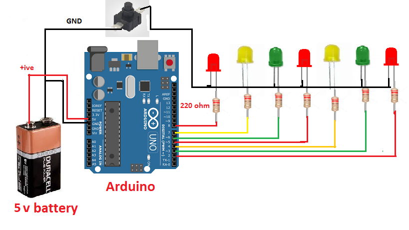
Circuit Diagram of Arduino LED chaser
Software

Hardware

Connections
- Connect the positive terminal of the battery to the 5V pin of Arduino.
- Connect the negative terminal of the battery to the ground pin of Arduino.
- Connect the 220-ohm resistor with the positive terminal of the LED.
- Connect the other terminal of a resistor from 1st LED at pin no 8 of Arduino
- Connect the other terminal of a resistor from 2nd LED at pin no 7 of Arduino
- Connect the other terminal of a resistor from 3rd LED at pin no 6 of Arduino
- Connect the other terminal of a resistor from 4th LED at pin no 5 of Arduino
- Connect the other terminal of a resistor from 5th LED at pin no 4 of Arduino
- Connect the other terminal of a resistor from 6th LED at pin no 3 of Arduino
- Connect the other terminal of a resistor from 7th LED at pin no 2 of Arduino
- Connect the negative terminal of all LEDs to the negative terminal of the battery.
Coding LED Chaser Circuit
int led[]={2,3,4,5,6,7,8};
void setup() {
for(int i=0;i<=8;i=i+1)
{
pinMode(led[i],OUTPUT);
}
}
void loop() {
for(int i=0;i<=8;i=i+1)
{
digitalWrite(led[i],HIGH);
delay(500);
}
for(int i=8;i>=0;i=i-1)
{
digitalWrite(led[i],LOW);
delay(500);
}
}