
The project aims to achieve FACTS (Flexible AC transmission system) using TSR (Thyristor Switch Reactance). This is done when the receiving end voltage is low while charging the transmission line. In the presence of a small load, a small current flows through the transmission line there so shunt capacitance becomes more effective. Due to the Ferranti Effect, the voltage at receiving end increases two times more than the voltage at sending end.
Every electrical apparatus can handle a certain voltage beyond that particular voltage level it will burn out. The increase in receiving end voltage due to the Ferranti effect can damage the electrical equipment. So, to control it we used a shunt reactor at the receiving end.
Transmission Line Inspection Robot
Working and Explanation
FACTS using TSR requires an operational amplifier that will generate lead time between zero voltage pulse and zero current pulse. This lead time is given to two interrupt pins of Arduino Uno. The Arduino program then initiates the shunt reactors for compensating for the voltage. The SCRs are arranged in series with Arduino Uno through optical isolation and are used for switching reactors.
How to design Automatic Hand Sanitizer
Components used:
The following components are used in Arduino based Ferranti effect overcome using a thyristor
- Thyristor
- Thyristor Switched Reactor
- Potential Transformer
- Current Transformer
- ZMCT103C AC Sensor
- Capacitor
- Voltage regulator
- LCD
- Arduino Uno
- Zero-Crossing Detector
- PCB and Breadboards
- Cables and Connectors
- Lamp
- Switch
GSM Based Smart Energy Meter With Theft Detection and Load control
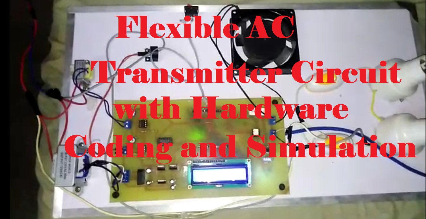
Circuit and Results (Flexible Ac Transmitter System Using TSR)
The image below is a simulation of Facts using TSR


First of all, we have converted the sinusoidal wave into square waves using an OP-amp amplifier or comparator circuit. Then the output of the comparator circuit is given to the XOR gate IC. From the truth table of the XOR gate when the input will be the same (00 or 11) then the output will be 0. Similarly when the input will be different (01 or 10) then the output will be 1. The result is given below

Before making hardware we have designed PCB of power factor improvement circuit.

The hardware of pf improvement using fact will look like this.

3D visualizer
we have discussed in detail about power factor correction using FACT.

Coding (Flexible Ac Transmitter System Using TSR)
// include the library code:
#include <LiquidCrystal.h>
// initialize the library by associating any needed LCD interface pin
// with the arduino pin number it is connected to
const int rs = 13, en = 12, d4 = 11, d5 = 10, d6 = 9, d7 = 8;
LiquidCrystal lcd(rs, en, d4, d5, d6, d7);
int lead = 3;
int triac = A4;
int button = A1;
void setup()
{
// set up the LCD’s number of columns and rows:
lcd.begin(16, 2);
Serial.begin(9600);
// Print a message to the LCD.
pinMode(lead,INPUT);
pinMode(button,INPUT);
pinMode(triac,OUTPUT);
digitalWrite(triac,LOW);
}
void loop()
{
// set the cursor to column 0, line 1
// (note: line 1 is the second row, since counting begins with 0):
int duration = pulseIn(lead,HIGH);
lcd.setCursor(10, 1);
//lcd.print(duration);
float duration1=(duration/1000);
float si=(duration1/20);
float phi=(si*360);
float power_factor=abs(cos(phi/57.2));
Serial.print(“phi:”);Serial.println(phi);
Serial.print(“power_factor:”);Serial.println(power_factor);
if(duration < 2000)
{
//lcd.setCursor(5, 1);
//lcd.print(” 1 “);
//lcd.setCursor(0, 1);
//lcd.print(“PF:”);
//delay(20);
//lcd.clear();
}
else
{
// print the number of seconds since reset:
lcd.setCursor(0, 1);
lcd.print(“PF:”);
lcd.setCursor(4, 1);
lcd.print(power_factor);
int read_button = digitalRead(button);
if(read_button == HIGH)
{
lcd.setCursor(0, 0);
lcd.print(” Normal Mode”);
digitalWrite(triac,LOW);
delay(20);
}
else
{
lcd.setCursor(0, 0);
lcd.print(“Compensation Mode”);
digitalWrite(triac,HIGH);
delay(20);
}
}}
we have tried to cover every aspect of “Flexible Ac Transmitter System Using TSR”. If you have any questions or need help in the project please do ask us in the comment section below.
Sir can plz you share the block diagram of this project???
Yeah I will soon share