
Electric Bicycle Controller using Arduino will control the speed of the motor with the throttle, basically, the throttle’s signal is analog in nature when the throttle is varied the current flows through it. The voltage level is measured by Arduino and based on that the PWM signal is sent to the ESC which drives the motor. The RPMs of the motor will be measured and displayed on the LCD, along with temperature and battery health.
How to Control Speed of Induction Motor using Variable Frequency Drive
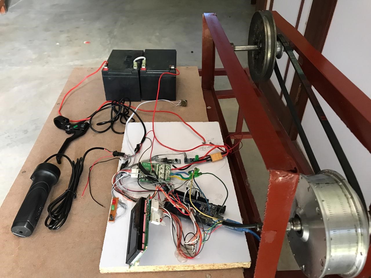
Working of Arduino based E bicycle:
In the Throttle-based Electric bicycle controller design, we have Arduino UNO our main controller. The temperature sensor is used to measure the temperature of the system. The current and voltage divider circuit is used to measure the current and voltage of the system. We have used a motor driver IC to run the motor in the circuit. The controller of the motor driver IC has four input pins and 2 enable pins if you want to use them then you have to enable them first. We are using three-phase so we will take three pins as our input pin. This IC will work on a certain voltage that will vary from 6 to 36 volt. You can use 6 MOSFET at the place of IC. In the simulation of bicycle design having throttle, we are using a motor driver circuit IC but in hardware, we will use MOSFET. Because there will be losses in the IC of the controller.
How to test VFD with multimeter?
Components used:
Following Components are used in our electric bicycle with throttle.
- Arduino
- 16*2 LCD
- Connecting wires
- BLDC Motor
- Throttle
- Temperature sensor
- Current sensor
- Voltage divider circuit
- Motor driver IC

Fig 1: Throttle Based Electric Bicycle Controller
We have used an oscilloscope for the waveform. From their result, we have noticed that the magnitude of PWM from Arduino was not enough to run this motor of the bicycle. After using the Motor driver IC magnitude of PWM was enough to run the motor in the circuit. As we have two scenarios where one is with using a hall sensor and the other is without using a hall sensor. The results of the bicycle controller are given below
Electric Bicycle Controller Circuit Diagram
The circuit diagrams of the bicycle controller are given below
Scenario 1 (without hall senor)
In the first scenario we have tried our circuit without hall sensor and didn’t get our desired results.

Fig 2: circuit without hall senor
Scenario 1 (Result)

Fig 3: When the throttle is 10%

Fig 4: When the throttle is 75%
Scenario 2 (with hall senor using a motor driver)
If you search on the Google you will find the same exact thing and it never works. That’s why i have decided to write in detail on the working of Electric bicycle controller using Arduino. In this scenario we have used Hall sensor in the circuit because of two reasons
- To see the position of rotor
- Also, to measure the RPM of the motor

Fig 5: Circuit with hall senor using motor driver IC
Scenario 2 (Result)


Fig 7: When the throttle is 75%
This proposed model is implemented on domestic level with limited specification. We design a system that is dependent on the throttle as well as the cruise. In future, there are many specifications that can be added to this proposed model. Instead of using BLDC motor in rear wheel, BLDC motor can be used in front wheel of the bicycle so that paddle can be used in addition with the battery to ensure the better working efficiency. Someone can add cadence sensor in which initially the speed is fixed by the user, peddle the bicycle and the rest of the energy is taken from the battery. In our proposed system, charging the battery is the major drawback we can design regenerative braking and mounted it on the bicycle so that the batteries are charged by solar energy. Also, we can use mid drive motors assisted by gears to further improve the efficiency.
Electric Bicycle Controller Programming:
#include “LiquidCrystal.h”
LiquidCrystal lcd(7, 6, 5, 4, 3, 2);
//voltage
float input_voltage = 0;
float val1=0.0;
float r1=100000.0;
float r2=10000.0;
float update1=0;
boolean vallue = 0;
//current
double offset = 2.5;
double sensor = 0.066;
double tension = 0;
float update2=0;
float input_current = 0;
float power=0;
//hall sensor
int hall_sensor_y = 13;
int hall_sensor_b = 12;
int hall_sensor_g = 8;
int abc;
int temppin= A2;
#define pot 0
#define pwm1 11
#define pwm2 10
#define pwm3 9
#define button 22
#define led 23
int motor_speed;
int motor_cruise;
int B=1;
void setup() {
Serial.begin(9600); // opens serial port, sets data rate to 9600 bps
lcd.begin(16,4); //// set up the LCD’s number of and rows columns :
pinMode(pwm1, OUTPUT);
pinMode(pwm2, OUTPUT);
pinMode(pwm3, OUTPUT);
pinMode(button,INPUT);
pinMode(hall_sensor_y, INPUT);
pinMode(hall_sensor_b, INPUT);
pinMode(hall_sensor_g, INPUT);
pinMode(led, OUTPUT);
}
void loop() {
for(int i=0;1;i++)
{
motor_speed= analogRead(pot)/4;
int hall_y = digitalRead(hall_sensor_y);
int hall_b = digitalRead(hall_sensor_b);
int hall_g = digitalRead(hall_sensor_g);
digitalWrite(led, LOW);
if (hall_y == 0 && hall_b == 0 && hall_g == 1)
{//001
analogWrite(pwm3, motor_speed);
analogWrite(pwm1, motor_speed);
analogWrite(pwm2, 0);
}
else if (hall_y == 1 && hall_b == 0 && hall_g == 1)
{//101
analogWrite(pwm1, motor_speed);
analogWrite(pwm2, motor_speed);
analogWrite(pwm3, 0);
}
else if (hall_y == 1 && hall_b == 0 && hall_g == 0)
{//100
analogWrite(pwm3, motor_speed);
analogWrite(pwm2, motor_speed);
analogWrite(pwm1, 0);
}
else if (hall_y == 1 && hall_b == 1 && hall_g == 0)
{//110
analogWrite(pwm1, motor_speed);
analogWrite(pwm3, motor_speed);
analogWrite(pwm2, 0);
}
else if (hall_y == 0 && hall_b == 1 && hall_g == 0)
{//010
analogWrite(pwm1, motor_speed);
analogWrite(pwm2, motor_speed);
analogWrite(pwm3, 0);
}
else if (hall_y == 0 && hall_b == 1 && hall_g == 1)
{//011
analogWrite(pwm3, motor_speed);
analogWrite(pwm2, motor_speed);
analogWrite(pwm1, 0);
}
//analogWrite(pwm3,motor_speed );
//analogWrite(pwm1,motor_speed );
//analogWrite(pwm2,0 );
//delay(10);
//analogWrite(pwm1,motor_speed );
//analogWrite(pwm2,motor_speed );
//analogWrite(pwm3,0 );
//delay(10);
//analogWrite(pwm2,motor_speed );
//analogWrite(pwm3,motor_speed );
//analogWrite(pwm1,0 );
//delay(10);
//_________________________________________________
//_________Cruise
vallue = digitalRead(button);
if (vallue == HIGH) {
for(int j=0;1;j++){
{
lcd.setCursor(0, 3);
lcd.print(“Cruise control “);
motor_cruise=motor_speed;
int hall_y = digitalRead(hall_sensor_y);
int hall_b = digitalRead(hall_sensor_b);
int hall_g = digitalRead(hall_sensor_g);
digitalWrite(led, HIGH);
if (hall_y == 0 && hall_b == 0 && hall_g == 1)
{//001
analogWrite(pwm3, motor_cruise);
analogWrite(pwm1, motor_cruise);
analogWrite(pwm2, 0);
}
else if (hall_y == 1 && hall_b == 0 && hall_g == 1)
{//101
analogWrite(pwm1, motor_cruise);
analogWrite(pwm2, motor_cruise);
analogWrite(pwm3, 0);
}
else if (hall_y == 1 && hall_b == 0 && hall_g == 0)
{//100
analogWrite(pwm3, motor_cruise);
analogWrite(pwm2, motor_cruise);
analogWrite(pwm1, 0);
}
else if (hall_y == 1 && hall_b == 1 && hall_g == 0)
{//110
analogWrite(pwm1, motor_cruise);
analogWrite(pwm3, motor_cruise);
analogWrite(pwm2, 0);
}
else if (hall_y == 0 && hall_b == 1 && hall_g == 0)
{//010
analogWrite(pwm1, motor_cruise);
analogWrite(pwm2, motor_cruise);
analogWrite(pwm3, 0);
}
else if (hall_y == 0 && hall_b == 1 && hall_g == 1)
{//011
analogWrite(pwm3, motor_cruise);
analogWrite(pwm2, motor_cruise);
analogWrite(pwm1, 0);
}
}vallue = digitalRead(button);
if (vallue== LOW){exit;break;}
}
}
//______________________________________________________________________________
//Conversion formula for voltage
int analog_value1 = analogRead(A1);
val1 = (analog_value1 * 5.0) / 1024.0;
input_voltage = val1 / (r2/(r1+r2));
if (input_voltage < 0.1) {
input_voltage=0.0;
}
if(input_voltage>update1)
{update1=input_voltage;}
//float E[100];
//E[B]=input_voltage;
//float Sum=0;
//current
double value = analogRead(A5);
tension= (value*5.0)/1024;
input_current= (tension- offset)/sensor;
if(input_current>update2)
{update2=input_current;}
if(millis()%50==0)
{
//voltage
//for(int C=1;C=B; C++)
//{Sum= Sum+E[C];}
//float avg=Sum/B;
update1=update1*1.1623;
lcd.setCursor(0, 0);
lcd.print(“Voltage=”);
lcd.print(update1);
//B=0;
//current
lcd.setCursor(0, 1);
lcd.print(“Current=”);
lcd.print(update2);
//power
power=update1*update2;
lcd.setCursor(0, 2);
lcd.print(“Power=”);
lcd.print(power);
input_voltage=0;
update1=0;
input_current=0;
update2=0;
power=0;
}
//B=B+1;
//______________________________________________________________________
//formula for temp
abc= analogRead(temppin);
float mv=(abc/1024.0)*5000;
float cel=mv/10;
lcd.setCursor(0, 3);
lcd.print(“Temp= “);
lcd.print(cel);
lcd.print(” *C”);
//_______________________________________________________________________
} }
In our proposed ‘throttle based electric bicycle controller using Arduino’ with cruise system, we design a system that is practical, efficient and cost effective. One of the key feature of this project is that it has the circuitry’s protection just in case if it gets heat up or current exceeds the specified limit, the controller will turn off the motor and protect any kind of damage. We design a model which is a cheap alternative to import the electric bicycle conversion kits and high custom duties. Most of the parts are easily available in the local market, although those parts are also imported but still it worth developing a local controller as it reduces the cost by huge amount.
Our project includes the display of various parameters like distance, speed, voltage, current and charging. If the battery health is below certain limit then it can be seen on the display. Also when we enter in the cruise system, the LED is on and the cruise control is shown on the display. Additionally, the motor and the driving circuitry will be protected against over current, over voltage and high temperature. If we work on this project a little bit more so that we can commercialized our project in the market and play a vital role in the clean and green environment.
Can you please share the code for the study purpose